4017 Ic Circuit

4017 ic circuit
IC 4017 is a digital counter plus decoder circuit. This pin goes high after the IC counts from 1 to 10. This is used as carry while counting. The IC can work from 3V to 15V, but normally powered with +5V to the Vdd/Vcc pin and the Ground/Vss pin is connected to ground.
How do I make a 4017 IC?
CIRCUIT DESCRIPTION
- pin 16 to positive rail of breadboard.
- pin 15 of IC4017 to pin 5 of IC4017.
- pin 13 of IC4017 to pin 8 of IC4017 then it goes to negative rail.
- connect 5 led with their cathode to negative rail and anode to 1,2,3,4, & 7 pins of IC 4017.
What is enable in 4017 IC?
Enable pin/Clock Inhibit(Pin 13) Enable pin enables the CD4017 IC. IC is enabled when the pin is active low. In order to disable or switch off the IC,this pin should be connected to active high input.
What is an IC 4017 decade counter?
The 4017 Decade counter is a device that counts clock pulses. It is called a decade counter because it has 10 outputs (Q0 to Q9) and so it can count 10 clock pulses before starting again. This is a very simple counter that is easy to understand and straightforward to use.
What is the use of 4017 IC?
The CD4017 IC is a CMOS Decade counter and it is used in the applications of low-range counting. This IC will count from 0 to 10 and the circuit with an IC 4017 will save board space as well as the time necessary to design the circuit.
How do I check my 4017?
Let's get started,
- Step 1: Take All Components As Shown Below. Components required -
- Step 2: Circuit Diagram. This picture is the scematic of this project.
- Step 3: Short Pins of IC. ...
- Step 4: Connect Buzzer. ...
- Step 5: Connect LED. ...
- Step 6: Connect Antenna. ...
- Step 7: Connect Battery Clipper Wire. ...
- Step 8: Connect Battery.
How do you make an LED chaser without IC?
How to Make Best LED Chaser Circuit Without IC
- Step 1: These Components Required to Make This Project.
- Step 2: Connect Emmiter of Transistors. ...
- Step 3: Connect 100uf Capacitors. ...
- Step 4: Connect +ve Pin of 3rd Capacitor. ...
- Step 5: Connect 560 Ohm Resistor. ...
- Step 6: Connect 10K Resistors.
How do you make a clock signal circuit?
Clock signal with a tone generator
- Set the generator to Sweep.
- Un-mute and set the generator's level to 0dB.
- Set the Start Frequency to 1000Hz and the Stop Frequency to 2000Hz.
- Set the Frequency Increments to 1 Octave.
- Set the Increment Time to the desired clock pulse speed, in milliseconds.
What is LED chaser circuit?
LED Chaser Circuit is a circuit in which the LEDs lights one by one for a period of time and the cycle repeats giving the running light appearance.
How do you read IC 4017 pinouts?
About IC 4017 It means, all its 10 outputs will go through one cycle of high output sequencing from start to finish in response to 10 clocks received at its input (pin#14). So in a way it is counting and also dividing the input clock by 10 and hence the name.
What is the working principle of counter?
Counter is a digital device and the output of the counter includes a predefined state based on the clock pulse applications. The output of the counter can be used to count the number of pulses. Generally, counters consist of a flip-flop arrangement which can be synchronous counter or asynchronous counter.
What is inhibit clock?
Clocking is inhibited when either of the clock inputs are held high, holding either input low enables the other clock input. This will allow the system clock to be free running and the register stopped on command with the other clock input.
Why do we use decade counters?
A decade counter counts ten different states and then reset to its initial states. A simple decade counter will count from 0 to 9 but we can also make the decade counters which can go through any ten states between 0 to 15(for 4 bit counter).
Why decade counter is used?
With each clock pulse the outputs advance to the next higher value, resetting to 0000 when the output is 1001 and a subsequent clock pulse is received. Decade counters are used in clock circuits, frequency dividers, state machines, and sequencers, just to name a few applications.
How does a decade counter work?
A decade counter counts in decimal digits, rather than binary. A decade counter may have each (that is, it may count in binary-coded decimal, as the 7490 integrated circuit did) or other binary encodings. A decade counter is a binary counter designed to count to 1001 (decimal 9).
What is LM358 IC?
LM358 IC is a dual operational amplifier integrated circuit with two Op-Amp powered by a common power supply. It consists of two independent compensated operational amplifiers with low power and high gain frequency. LM358 is specially designed to operate from a single supply over a wide range of voltage.
What are counter circuits used for?
Counters are used not only for counting but also for measuring frequency and time ; increment memory addresses . Counters are specially designed synchronous sequential circuits, in which , the state of the counter is equal to the count held in the circuit by the flip flops.
Which IC used in counter?
A counter IC is an IC that can count externally input clock pulses. ABLIC's counter IC can read the counter data via the I2C-bus interface. This capability supports the development of a variety of measuring instruments, infrastructure meters, amusement devices, life counters, etc.
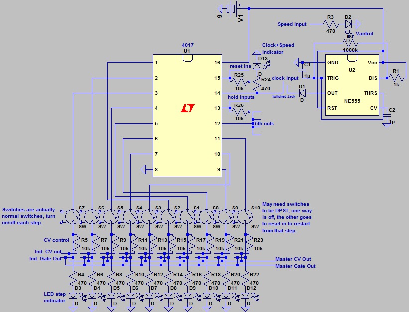
How does the 555 timer IC compliments the decade counter CD4017 IC?
CD4017 Example Circuit – Running LEDs A 555 Timer is set up in astable mode, which makes it into an oscillator circuit that creates a clock signal. This clock signal goes into the clock input of the IC 4017. Every time the clock input goes high, the counter in the 4017 increases, which makes the next output HIGH.
Can LED run without resistor?
Never Ever Connect an LED Without a Resistor, Mostly. When hooking up an LED, you are always supposed to use a current-limiting resistor to protect the LED from the full voltage.
12 4017 ic circuit Images
17 Best images about Mini Electronics Projects on Pinterest Sensor

Knight Rider circuit with 4017 ic YouTube Knight rider Circuit Rider

Traffic Light Control Electronic Project using 4017 555 Timer

Pin on 4017

CD4017 Decade Counter with 10 Decoded Electronic schematics

Pin on Electronic Projects
4017 based sequencer Electronic schematics Eurorack diy Diy electrical

5 Stage Johnson Counter Using 4017BP IamTechnicalcom Circuito

Pin on Electronic Projects

Sequential LED flasher using IC 4017 and 555 Power amplifiers

How to Understand IC 4017 Pinouts Circuit Projects Something To Do
Post a Comment for "4017 Ic Circuit"